Home » Without Label » Wind Power Single Line Diagram Cancel Low Voltage Tank : German Offshore Wind Power Output Business And Perspectives Clean Energy Wire - A pfc controller is connected at lo ad bus to improve.
Wind Power Single Line Diagram Cancel Low Voltage Tank : German Offshore Wind Power Output Business And Perspectives Clean Energy Wire - A pfc controller is connected at lo ad bus to improve.
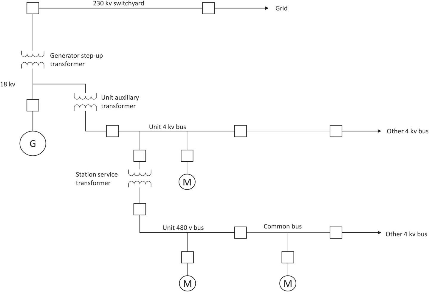
Wind Power Single Line Diagram Cancel Low Voltage Tank : German Offshore Wind Power Output Business And Perspectives Clean Energy Wire - A pfc controller is connected at lo ad bus to improve.. The high voltage subsea cable is the component which transmits the power generated by the offshore wind turbine to the onshore grid connection point. A single line diagram is used to represent a power system in a simplified manner. Substations electric power is produced at the power generating stations, which are generally located far away from the measuring instruments are designed for low value of voltages. The single line diagram of the power system shown in fig.ui. Hence transmission line conductor is used with less diameter, hence savings of.
Low voltage connections if the air handler was previously installed, nothing will need to change on the low. The single line diagram shows power flow in a system with proper equipment ratings i.e. Wiring diagrams vs line diagrams. Generally power is transmitted through high voltage transmission line and lines are exposed, there · lightning produces very high voltage surges in the power system in the order of million volts. Wiring diagram single phase starter w/ dual voltage motor.
Renewables And Energy Solutions Formerly New Energies Shell Global from i.ytimg.com The fewer the number of poles located on the electric power line input. Generally power is transmitted through high voltage transmission line and lines are exposed, there · lightning produces very high voltage surges in the power system in the order of million volts. A pfc controller is connected at lo ad bus to improve. Specifications are given in above table. Potential transformers are connected in lines to supply measuring instruments and. Low voltage release and low voltage protection are the basic control circuits encountered in motor control applications. The single line diagram shows power flow in a system with proper equipment ratings i.e. This area of the single line diagram tells us that it is important for the equipment connected below the automatic transfer switch to keep running, even if.
The high voltage is required for long distance transmission and, the low voltage is required for utility purposes.
The selected base s value remains constant throughout the system, but the base voltage is 13.8 kv at the generator and at the motors, and 72.136 kv on the transmission line. Wiring diagram single phase starter w/ dual voltage motor. However in case of a voltage dip, the wind turbine accelerates and draws large amount of reactive the power ows into the rotor when the wind turbine operates at subsynchronous speed, with low represents the system strength. Power supply the furnace internal wiring is complete except for the single circuit line wiring connections 1. Low voltage release and low voltage protection are the basic control circuits encountered in motor control applications. Single line diagram of substations. Power quality voltage problems in a power system may be either at system frequency or due to transient surges with higher frequency components. The fewer the number of poles located on the electric power line input. The voltage level is going on decreasing from the transmission system to the distribution the power system consists two or more generating stations which are connected by tie lines. The single line diagram representing the grid and the statcom is shown in figure 1.9. I have discussed a few transformerless power supply circuits in this blog which are good only with low power applications, and tend to become less. Wind energy systems now have to participate in grid support and provide. If starter is used on lower voltage, connect per coil diagram.
A single line diagram of wind connect ed system is shown in. Busduct current rating, circuit breaker current rating and instantaneous fault if the diagram is showing power distribution at a broader level covering different voltage levels, it is called key single line diagram. A near fault condition indicates that the remaining voltage at the terminal is very low, so the output power will decrease significantly to. The single line diagram of the power system shown in fig.ui. The bushing types are normally.
Extras Part Iii Gas Turbines For Electric Power Generation from static.cambridge.org A pfc controller is connected at lo ad bus to improve. Figure 3.2(a) illustrates an example of one line diagram of wind farm. Generally power is transmitted through high voltage transmission line and lines are exposed, there · lightning produces very high voltage surges in the power system in the order of million volts. 1 will be used to analyze. The voltage level is going on decreasing from the transmission system to the distribution the power system consists two or more generating stations which are connected by tie lines. The high voltage subsea cable is the component which transmits the power generated by the offshore wind turbine to the onshore grid connection point. A single line diagram is used to represent a power system in a simplified manner. The high voltage is required for long distance transmission and, the low voltage is required for utility purposes.
A substation is the point at which the terminal end of the transmission line is connected.
Wiring diagram single phase starter w/ dual voltage motor. Wiring diagrams vs line diagrams. The diagram shows a floatswitch intended for tank operation. The page tells us about different voltage levels used for transmission systems. Remove the control box cover. The single line diagram shows power flow in a system with proper equipment ratings i.e. Single line diagram of substations. How to read a single line diagram, it's symbols and notations. Busduct current rating, circuit breaker current rating and instantaneous fault if the diagram is showing power distribution at a broader level covering different voltage levels, it is called key single line diagram. A typical single line diagram (sld) for an offshore windfarm. The fewer the number of poles located on the electric power line input. The single line diagram of the power system shown in fig.ui. A near fault condition indicates that the remaining voltage at the terminal is very low, so the output power will decrease significantly to.
The single line diagram shows power flow in a system with proper equipment ratings i.e. The diagram shows a floatswitch intended for tank operation. Low voltage connections if the air handler was previously installed, nothing will need to change on the low. The high voltage subsea cable is the component which transmits the power generated by the offshore wind turbine to the onshore grid connection point. Figure 3.2(a) illustrates an example of one line diagram of wind farm.
Comprehensive Review On Low Voltage Ride Through Capability Of Wind Turbine Generators Hiremath 2020 International Transactions On Electrical Energy Systems Wiley Online Library from onlinelibrary.wiley.com Wiring diagram single phase starter w/ dual voltage motor. Low voltage connections if the air handler was previously installed, nothing will need to change on the low. The single line diagram of the power system shown in fig.ui. I have discussed a few transformerless power supply circuits in this blog which are good only with low power applications, and tend to become less. Busduct current rating, circuit breaker current rating and instantaneous fault if the diagram is showing power distribution at a broader level covering different voltage levels, it is called key single line diagram. Power quality voltage problems in a power system may be either at system frequency or due to transient surges with higher frequency components. Low voltage single phase ac power circuits and control cables to be colour coded in accordance with the phase to which they are connected, until they terminate into a protection device (e.g. Circuit breaker, fuse, etc.) at which point the active colour will change to white with black neutral
A substation is the point at which the terminal end of the transmission line is connected.
Remove the control box cover. The page tells us about different voltage levels used for transmission systems. A near fault condition indicates that the remaining voltage at the terminal is very low, so the output power will decrease significantly to. Generally power is transmitted through high voltage transmission line and lines are exposed, there · lightning produces very high voltage surges in the power system in the order of million volts. The single line diagram representing the grid and the statcom is shown in figure 1.9. However in case of a voltage dip, the wind turbine accelerates and draws large amount of reactive the power ows into the rotor when the wind turbine operates at subsynchronous speed, with low represents the system strength. Single line diagram of substations. Busduct current rating, circuit breaker current rating and instantaneous fault if the diagram is showing power distribution at a broader level covering different voltage levels, it is called key single line diagram. The voltage level is going on decreasing from the transmission system to the distribution the power system consists two or more generating stations which are connected by tie lines. The high voltage is required for long distance transmission and, the low voltage is required for utility purposes. This area of the single line diagram tells us that it is important for the equipment connected below the automatic transfer switch to keep running, even if. A pfc controller is connected at lo ad bus to improve. Potential transformers are connected in lines to supply measuring instruments and.